
PGL50H
Model
AXP50Ean
6971390271704Price
$ 1000
PANGOMICRO Titan-2 PG2T390 FPGA SoM Core Board DDR4 Industrial Grade P390
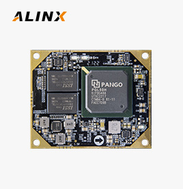
PANGOMICRO Logos2 PG2L100H SoM Core Board Industrial Grade P100
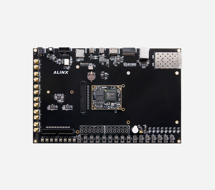
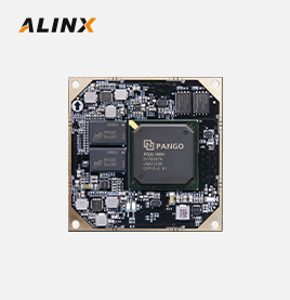
PANGOMICRO Logos PGL50H FPGA SoM Core Board Industrial Grade DDR3 P50
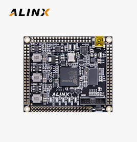
PANGOMICRO Logos PGL22G SOM FPGA Core Board P25G
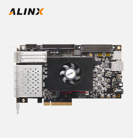
PANGOMICRO Titan-2 PG2T390 FPGA Development Board Evaluation Boards & Kits PCIe Optical Communication DDR4 FMC AXP390
Can be used for graduation projects, electronic competitions, product development, suitable for teaching fields such as fiber optic communication, measurement and control, electronics, industrial control, etc

Supporting Verilog HDL Demos and Docuemnts, All Doucments Saved in Dropbox, after buy the board, email to get it.
01. Pango Design Suite 2020.3 Installation
02. LED water lamp experiment and simulation
03. Key detection experiment
04. Dial switch experiment
05. PLL phase-locked loop output test
06. Serial port Transmitting and Receiving experiment
07. Key debounce experiment
08. Buzzer Experiment
09. Relay controlled fan experiment
10. I2C Interface EEPROM Experiment
11. LM75 temperature testing experiment
12. SD Card Read and Write Experiment
13. FLASH Reading and Writing Experiment
14. Nixie tube display hour minute second
15. Dial switch Nixie tube displays Decimal number
16. HDMI color bar output
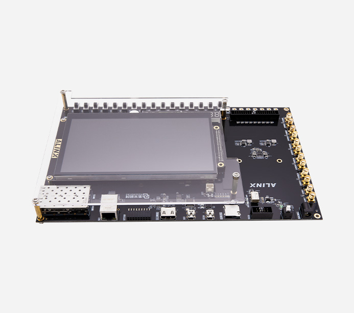
17. 4.3-inch screen color bar output
18. 7-inch screen color bar output
19. DDR3 read and write data test
20. AN831 Recording and Playback
21. SD Card Music Player Experiment
22. Character HDMI display
23. Character 4.3 inch screen display
24. Character 7-inch screen display
25. SD card image HDMI display
26. SD card image displayed on a 4.3-inch screen
27. SD card image displayed on a 7-inch screen
28. Binocular camera captures HDMI display
29. Binocular camera captures a 4.3 inch screen display
30. Binocular camera captures 7-inch screen display
31. Camera edge detection HDMI display
32. Camera edge detection 4.3 inch screen display
33. Camera edge detection 7-inch screen display
34. AD9238 waveform display
35. AD7606 waveform display
36. ADDA Test Routine
37. AD9767 dual channel sine wave generation
38. AD9767 dual channel triangular wave generation
39. RTC clock displays time every 1 second
40. Real-time clock HDMI dynamic display
41. LVDS experiment
42. Gigabit Ethernet transmission
43. AD9280 Ethernet transmission
44. AD7606 Ethernet transmission
45. AD9280 Ethernet transmission
46. Single camera capturing Ethernet transmission video
47. Binocular camera captures Ethernet transmitted video
48. USB bidirectional speed measurement routine
49. 1.25g fiber optic communication testing
50. 5g fiber optic communication testing
51. Camera video acquisition fiber 5G transmission test
52. CTC mode testing of fiber optic communication HSST
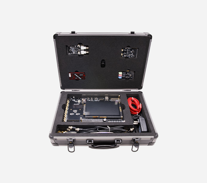
FPGA board
7-inch display screen
12bit AD acquisition module
14bit DA acquisition module
5 megapixel camera
Audio module


Learn More about the Core Board, Click to View>>

FPGA Chip
PGL50H-6IFBG484
Chip level
Chip speed level 6, chip temperature level industrial grade
Flip-Flop (FF)
64200
LUT5
42800 (LUT5=1.2LUT4)
DRM (18Kbits)
134
APM Unit (Multiplier)
84
PCIe Gen2x4
1
HSST
4x 6.375Gb/s max
PLL
5
AES
1
DDR3
2x 512MB, 32bit
QSPI Flash
128Mbit QSPI FLASH
Crystal Oscillator
125MHz active differential crystal
50Mhz differential crystal oscillator
SFP
2-way SFP fiber optic interface, with each fiber optic data communication receiving and sending speed up to 6.375Gb/s
HDMI Output
support 1080P@60Hz Output, supporting different formats
Gigabit Ethernet
One gigabit Ethernet interface for data exchange with computers or other network devices
40-Pin Expansion Ports
Two expansion ports with a spacing of 2.54mm and 40 pins, capable of connecting various external modules (binocular camera, LCD screen, AD module, etc). The expansion port includes 1 channel for 5V power supply, 2 channels for 3.3V power supply, 3 channels for ground, and 34 channels for I/O ports
USB2.0
1-way USB2.0 interface for high-speed communication between development board and PC
Uart
1-way Uart to USB interface for communication with computers, facilitating user debugging
CMOS
18-pin camera interface that can connect to a 5 million OV5640 camera
SMA
18-pin camera interface that can connect to a 5 million OV5640 camera
JTAG
10-pin 0.1-inch Standard JTAG Port for Programs Debug and Download
Nixie tube
12 digit Nixie tube is integrated on the board, which can dynamically display 12 digits
Temperature sensor
1 temperature sensor chip LM75 to detect ambient temperature
EEPROM
EEPROM 24LC04 with IIC Interface On-Board
RTC
One way RTC Real-time clock, equipped with a battery holder, and the model of the battery is CR1220
SD Card Slot
1 Micro SD Card Slot, Support the SPI Mode
LED
8 User LEDs
KEYs
8 User Keys
Dial switch
16 channel pull-out switch, which can be used to simulate multiple signal inputs
relay
Two relay outputs can be used for signal physical isolation testing.
buzzer
1 channel buzzer, which can be used for acoustic experimental testing.
other
The I2C and SPI interfaces are introduced on the board, which can be used by customers to connect their own peripherals.
Voltage Input
+12V DC
Power Adapter
12V / 3A
Current Input
Max. Current 3A
AXP50
1
AN970
1
AN9238
1
AN9767
1
AN5640
1
AN831
1
USB downloader
1
Ethernet cable
1
optical cable
1
TF card
1
card reader
1
SMA to BNC cable
2
Mini USB Cable
2
10-pin JTAG flat cable
1
BNC Cable
2
SMA Elbow connecting line
4
12V power supply
1
Transparent protective board
1
Learn More about the Core Board, Click to View>>

Size Dimension
280mm x 180mm
Number of Layers
14-Layer Core Board PCB, 8-Layer Carrier Board PCB


High speed fiber optic communication, video processing, high-speed data transmission processing, etc

Rich peripheral interfaces: 2-way fiber module interface, 2-way high-speed transceiver SMA interface, 1-way HDMI output interface, 1-way Gigabit Ethernet interface, 1-way high-speed USB2.0 interface, 1-way Uart interface, 1-way camera interface, 2-way 40-pin expansion port, etc. Support high-speed fiber network communication, high-speed data storage, video image processing, project pre validation, machine vision, and industrial control applications in multiple fields
Fiber optic data communication can receive and send data at speeds up to 6.375Gb/s

MIPI camera module on machine display diagram

Camera module for video capture, displayed on the monitor through the HDMI output interface of the development board
AN9767/AN706 Module On-Board Demo

*The Signal Source Output Signal is Connected to the AN9767 Module, and the Waveform Signal is Displayed through the Oscilloscope
*The Signal Source Output Signal is Connected to the AN706 Module, Run the System to Draw the Waveform Data, and is Displayed to the Monitor through the HDMI Interface of the FPGA Development Board
The warranty period of all products sold is 12 months, of which FPGA chips and LCD screens are wearing parts and are not covered by the warranty. All accessories and gifts are not covered under warranty.
Links:


Alinx Electronic Technology (Shanghai) Co., Ltd. 滬ICP備13046728號


